Reviewing yesterday’s notes, I should add that the use of the supplied value ‘_eusrstack’ from the MRS2 linker script is only necessary until such time as I replace it with my own linker script. This will happen in due time.
Examining the processor’s registers, not the peripheral registers, can be enabled while debugging by enabling ‘Disassembly view’. Right-click in the editor area and select ‘Open Disassembly View’. On the right-hand side of the Disassembly view is the ‘Variables’ section, with Local, Global, Static and Registers as collapsed lists. Expand the ‘Registers’ list to see the processor register contents, which also includes the program counter (pc) and CSRs. Double-click on a register in the listing and you can edit the value in real time. Handy!
Now I never claimed to be a CSR expert but there are some CSRs in this list that I have yet to meet, e.g., ‘vcsr’ and ‘seed’. A check for the latest QingKeV4 Microprocessor Manual on the WCH web site gives me V1.3, which is later than the V1.2 I already had.
A quick reminder to myself: The CH32X035 is based on the QingKe V4C core, with RV32IMAC instruction set with some vendor-proprietary extensions. It supports ‘machine’ and ‘user’ mode privilege levels, but not ‘supervisor’. Changing modes is briefly described in Section 1.3, p. 2. I have yet to have a compelling reason to enter ‘user’ mode. One day.
Note: I happened to notice this when I first started debugging my test program and saw that the sp register was 0x20002800. Once it had actually executed the instruction I had specified, the sp was 0x20005000, as would be expected. I don’t know where this value came from.
There are several taxonomic schemes involved with the naming and addressing of the CSRs. It’s all very fascinating and something I will need to understand more fully in the near future. I don’t actually need them for my immediate goals today, which are:
1.  Configure system clock for 48 MHz
2.  Output system clock on MCO, PB9
3.  Configure GPIO ports
4.  Blink LED(s)
5.  Configure USART
6.  Fake reset signal using PB4 or 'Download' push button.
Beyond that I will need to extract the register definitions from the SVD, as the novelty of looking up all the addresses and bit positions will have worn thin.
I also see that the RST signal is an alternate function of PB7.
In other news, the i8 battery is still running! The i8 is a small, wireless mouse and keyboard with a rechargeable battery that I am evaluating for this project.
So step 1 involves writing to a couple of registers in the RCC peripheral, so I will need to look up the base address in the RM, Section 1.2 Memory Map, Figure 1-2 Storage image, which is an excellent reference for all the base addresses of peripherals on the chip.
RCC starts at address 0x40021000, so I will load that indirectly into one of the pointer registers, even though I can use any of the registers for this. But which one to use? I had been using the ‘thread pointer’, or tp register, also known as x4. I have also used the global pointer, gp/x3 and frame pointer fp/s0/x8. But which one is the right one? Does it even matter? It turns out that there are documents that cover these questions. A proposal for an embedded application binary interface (EABI) is published here:
In the meantime, since it absolutely does not matter, I will use t0/x5 as the base address for accessing peripherals.
Interestingly, the compiler has no problem using a single lui instruction to load the t0 register with a constant value (the base address of the RCC block) when I used the ‘la’ load address pseudo-instruction, where it wanted to use the auipc/mv combination for the stack pointer initialization. Also, the sp showed up initially as 0x20002800 again. Weird.
Oddly, the Register list shows some values in hexadecimal and some in decimal. I’m not finding a control to allow me to tell it which one I want. The sp is showing in hex but t0 is in decimal, 1073876992, which is valid but unintuitive.
And it seems the ‘Disassembly view’ is not required to be up to see the register values.
So to know which bits to flip in the RCC registers to get the results I want, I spent some quality time reading the RM. The CH32X035 has a vastly streamlined clock system when compared to any of the other devices on offer. It has one clock source, in internally generated RC oscillator, HSI, that operates at 48 MHz. There are no other options. There is no support for external oscillators (HSE) of any sort. There are no PLLs. There is also no support for any low speed oscillators, internal or external.
The HSI is characterized at the factory and a fixed adjustment value is burned in somewhere. The device loads this value and programs the HSICALC field of the RCC_CTLR automatically. The frequency can be further trimmed using the HSITRIM field of the RCC_CTLR.
There is a clock prescaler called the HB clock source prescaler, but it applies to the entire system and not just the HB bus. The default setting is /6 so the system is running at 8 MHz on boot. The only other option in the RCC_CFGR0 register is the selection of MCO output signal. The two choices are SYSCLK (4) or HSI (5).
So to select 48 MHz system clock, I need to write a zero into the HPRE field. To select system clock as the MCO output, I need to write a 4 into the MCO field.
To do that, I need to define the needed bits in their proper positions and just write that to the RCC_CFGR0.
RCC_MCO_SYS = (4 << 24)
RCC_MCO_HSI = (5 << 24)
The ’24’ is the bit position of the beginning of the bit field within the RCC_CTLR.
Writing just that value to RCC_CFGR0 will effectively also set the HPRE to zero, which is what I want.
I will also have to define the offset of the RCC_CFGR0 register from the base address.
It seems to run, but I will have to swap items 2 & 3 if I really want to see the MCO on PB9, as it is, by default, an input.
So I define the base addresses of both GPIOA and GPIOB, then define the offsets to the CFGLR and CFGHR configuration registers.
And then I got stuck for several hours. Odd things were happening, and none of them involved a square wave signal of any kind on the MCO.
First, the Register view may or may not update in real time. I created another control project just to enable the MCO output and see if that works. Yes, it works.
Along the way I see that there is only one speed setting available for the GPIO pins and that is 50 MHz. I don’t know what that means.
Next, I found that things worked better when I did not try to set the system clock to 48 MHz. Leaving it at the boot default of 8 MHz makes everybody happy.
So now I have to read the flash memory section and see how to turn on the prefetch buffer, which is mentioned in the HPRE field settings as a footnote, but that phrase ‘prefetch buffer’ is not to be found elsewhere in the RM. I think it might be referring to the wait-state setting for flash access.
Yes, the FLASH_ACTLR register contains a single field, LATENCY. It suggests 0 wait states for HCLK <= 12 MHz, 1 wait state for 12 MHz < HCLK <= 24 MHz and 2 wait states for 24 MHz < HCLK <= 48 MHz. So to run successfully at 48 MHz, we need to set the LATENCY field to 0x02 in the FLASH_ACTLR.
So now we have a very rounded wave of ~47.76 MHz coming out of the MCO. The LED is blinking pretty quickly, as well, but stepping it in debug mode shows it going on and off as expected. So that’s the first 4 steps accomplished.
To set up the USART, we need to enable its peripheral clock first, then configure it in the normal manner. This particular peripheral is not hard to set up for very basic communication.
So that’s 5 of six goals so far today. Since the sixth and final goal as previously outlined involves setting up interrupts and who knows what else, I will postpone it until tomorrow. However, at that point, I might decide that it would be more productive to proceed with the distillation of the SVD and not have to do the tedious transcription of addresses and bit maps by hand.
I’ve been working on a small embedded project for a customer and have been keeping copious notes on my progress. It’s using (for the moment) a WCH CH32X035 RISC-V microcontroller. I have some experience with other members of the CH32V family, including the -003, -203, -208 and -307. The CH32X035 is new to me and I wanted to get to know it a little better.
I started these notes back on 25 January 2025. They are quite detailed and if you’re not especially interested in embedded software and hardware development, it just might not be very interesting to you. You have been warned.
For the brave or bored amongst you that continue on, I welcome your feedback, questions and comments. Please note that as these are literally ‘lab notes’, I will sometimes commit the twin composition sins of using incomplete sentences and ending sentences with prepositions. Please forgive me.
24 January 2025
Currently using a WCH “official” development board, the CH32X035G8U6-EVT-R0, marked on the silkscreen as CH32X035G8U6-R0-1v2. An unfortunately placed via takes out a critical segment of the ‘8’, making it look like a ‘6’. There is no -G6 variant offered at this time.
The device is a CH32X035G8U6, which is no surprise, in a QFN28 quad flat no-leads 28 pin package. It’s very small and has a 4mm x 4mm x 0.75 mm outline. I believe there is a solder pad on the bottom connected to ground.
The board has no reset switch. It does have a pushbutton marked ‘Download’ to select the bootloader when power is applied. This pushbutton, identified as S4 on the schematic, is connected to PC17 on one side and to Vcc via a 4.7KΩ resistor, R5.
Researching the ‘boot’ mode raises more questions than it answers:
Q: Can the boot code region be over-written with user code?
Q: What interfaces are supported by the boot mode?
Q: Where is the boot mode documented?
Q: What is TURBO mode (see FLASH status register)?
I have also seemingly arbitrarily attached the RST line from the WCH-LinkE device programmer to pin PB4. PB4 happened to be between the transmit and receive pins of USART1 on the board headers, and having a ‘solid’ three pin connector tends to hold on better than two individual pins. My thinking at the time I built the programming cable for this board was that I would use an external IO interrupt to trigger a software device reset. I could do that as well with the PC17/Download button, while retaining whatever bootloader capabilitiesof the chip during the power-on sequence.
I have not yet read the RM in detail, but have just ‘accidentally’ learned that the device boots with the internal 48 MHz RC oscillator divided by 6, for a system clock of 8 MHz. What’s very interesting to me at the moment is how can this clock with a specified frequency accuracy of ~0.8% be used as the clock for a proper USB host or device, as USB has a much tighter allowable timing tolerance.
The immediate goal of this investigation is to see if it is possible to program the device to operate as a USB host and take input from a standard USB keyboard and possibly a mouse. This is in furtherance of a bespoke project involving an OLED with the ability to edit custom messages in situ, without requiring connection to a proper computer or other complexity.
This will also further a separate goal of a completely self-hosted development system based on these devices.
So the first steps will be attempting to use MounRiver Studio 2 (MRS2) to compose, assemble, program and debug an application written entirely in RISC-V assembly language.
The next big step will be to extract the device register information from the vendor-supplied SVD file and format it as an assembly language ‘include’ file.
Due to the limited aspect of the initial project requirements, I think that the vector-table-free (VTF) mechanism for assigning interrupt vectors will suffice:
HardFault
USB
EXTI
I2C
The final list might necessitate the use of a traditional vector table for interrupts.
I have created a new MRS2 project called G8-asm, which is actually a C language-based project, as that is the MRS2 default. The supplied code prints the system clock frequency and chip ID code to the debug console on USART1, then sets up GPIO pin A0 as an output, then goes into an endless loop toggling the GPIO pin. I have jumpered pin A0 to the provided LED1 connector on the board, and it does, indeed, flash the red LED at ~1 Hz.
I will, for now, preserve the supplied Startup/startup_ch32x035.S file and dispose of the remaining source code from the project. This leaves in place the vendor-supplied linker script in Ld/Link.ld and whatever project settings were created when I asked for this project to be created.
Deleting the following project folders and their contents:
/Core
/Debug
/Peripheral
/User
Let’s see how well MRS2 likes my changes. The linker complains of undefined references to:
SystemInit
main
Which is fair enough, as they certainly no longer exist within the project.
Note: The internal comment in the provided startup file lists the filename as startup_ch32x035.s with a lower case ‘.s’ as the file extension when in actuality it is startup_ch32x035.S with an upper case ‘.S’ file extension, which is correct. The GNU assembler treats the two differently, with the ‘.s’ extension omitting any macro substitutions. We certainly want the ‘.S’ because a lot of the heavy lifting in this project is done with macro definitions.
Commenting out the final four lines of the startup_ch32x035.S eliminates the linker’s complaints and a small but effectively useless application is created.
#    jal  SystemInit
#   la t0, main
#   csrw mepc, t0
#   mret

text data bss dec hex filename
380 0 2048 2428 97c G8-asm.elf
I’ll add an infinte loop at the end and then try to debug it.
1: j 1b # loop
And it does work, and allows me to step through individual instructions in the source code.
Reminder: the GNU assembler supports both /* comments */ and # single line comments.
Adding a new source file, G8-asm.S, to the project directory does not automatically add it to the list of source files to be assembled. Moving G8-asm.S to the Startup folder doesn’t help.
The file itself is quite humble at this point:
# G8-asm.S
# part of G8-asm project
# 24 January 2025 - Dale Wheat

# G8-asm.S [end-of-file]
OK, after flailing about and even some Stack Overflow browsing, I accidentally discovered that if you remove/delete the ‘obj’ folder from the project, then add the file to the project, it finds it and incorporates it into the project correctly. Using the project ‘clean’ target does the same thing. So there’s two ways out of this particular pickle.
So now I begin harvesting the useful bits of startup_ch32x035.S and transplanting them into my new G8-asm.S file, beginning with the ‘_start’ symbol, required by the GNU linker. I suppose it can be called something else, and the linker of course needs to know where to ‘_start’. The ‘-e [name]’ command line option for the linker lets you rename it.
I also ‘dis-included’ the startup_ch32x035.S file from the project until I’ve extracted what I need from it.
You also have to declare the _start label as global, which is done like this:
.global _start
Interestingly, it need not precede the actual label. I don’t know how to combine the two things into a single statement, however. That’s the dream, isn’t it?
So the first actual thing I want the code to do is to set up the stack pointer to the end of SRAM. The MRS2 basic linker script has a complex formula that allows for a designated memory ‘heap’ for dynamic allocation as well as a specified stack size. I’m just going to use the physical end of SRAM, which on this part is 0x20005000. Technically, it’s one byte before that, 0x20004FFF, but the customs of the ABI are to decrement the stack pointer first, then store values (a stack ‘push’) then take off values and adjust the stack pointer back up afterward (a stack ‘pop’).
The MRS2 linker script defines a variable ‘_eusrstack’ (end of user stack) that happens to be the end of physical SRAM on this chip, i.e., 0x20005000. So this statement:
la sp, _eusrstack # initialize the stack pointer
will do the trick, but ‘la’ (load address) is actually a pseudoinstruction and breaks down into two ‘real’ instructions:
la sp, _eusrstack # initialize the stack pointer
0: 20005117 auipc sp,0x20005
4: 00010113 mv sp,sp
The ‘mov sp,sp’ is only there because it thinks it needs to load the lower 12 bits as well, even when they are zero and the auipc instruction has already set them to zero.
This works:
lui sp, %hi(_eusrstack)
where the %hi() notation is called a RISC-V assembler modifier. It extracts the upper 20 bits of the constant, which happens to be all we need, as the lower 12 bits are all zero.
So now that I can debug these programs, I need to figure out how to see the contents of the registers while the program is executing.
Yes, the year 2022 is upon us and it has been “a while” since I updated this blog. A very kindly-written email that I received a few days ago reminded me that it had been so long, in fact, that there was some doubt of my continued existence. Please allow this short note to serve as notice that I am still here, still working on Important Scientific Research and still operating my little electronics boutique.
What have you been up to since we last talked? I’d really like to know. Drop me a note in your preferred style and catch me up!
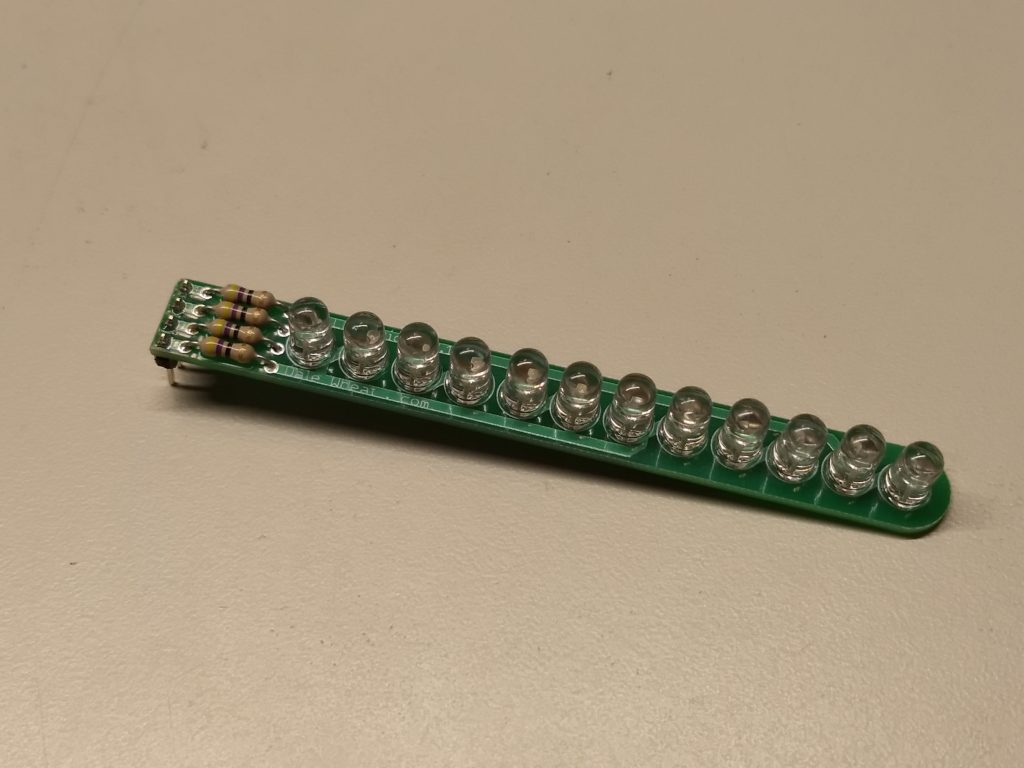
The 12LEDstick is a multiplexed (specifically Charlie-plexed) linear array of twelve bright blue LEDs. It uses four (4) pins to control all twelve LEDs, making it easy to add a lot of LEDs without dedicating a lot of valuable I/O lines. An Arduino library with example sketches is provided to make it easy to add to your next blinky project.
Why do it?
Adding multiple LEDs to a project makes it more visually interesting, useful and engaging. Using a clever multiplexing technique called Charlie-plexing allows up to 12 LEDs to be controlled with only four (4) signals. The LEDs can be mounted directly to the provided PCB for a compact linear array or wired individually to reach wherever you need extra blinky-ness!
Value/Benefit
Wiring up a lot of LEDs can require a correspondingly large number of connections and extra components. The 12LEDstick reduces this to four connections and four current-limiting resistors (provided). The Arduino library and examples sketches will get your project blinking fast and easy.
Who benefits?
Electronic hobbyists can easily add large numbers of LEDs to their projects without needing extra chips, shift-registers, resistors and wiring. Arduino builders can easily add more blinky bling without using up all the precious I/O lines. Any microcontroller that can sink or source 10mA per I/O pin can drive the 12LEDstick.
The 12LEDstick is a multiplexed linear array of blue 5mm LEDs that can be controlled with only four signals. An Arduino library and samples sketches are provided.
Today I have the pleasure to tell all you Good People that there is a new product available in the store. Without further ado, allow me to present the Barrel Jack Breakout board kit!
Barrel Jack Breakout
What is it?
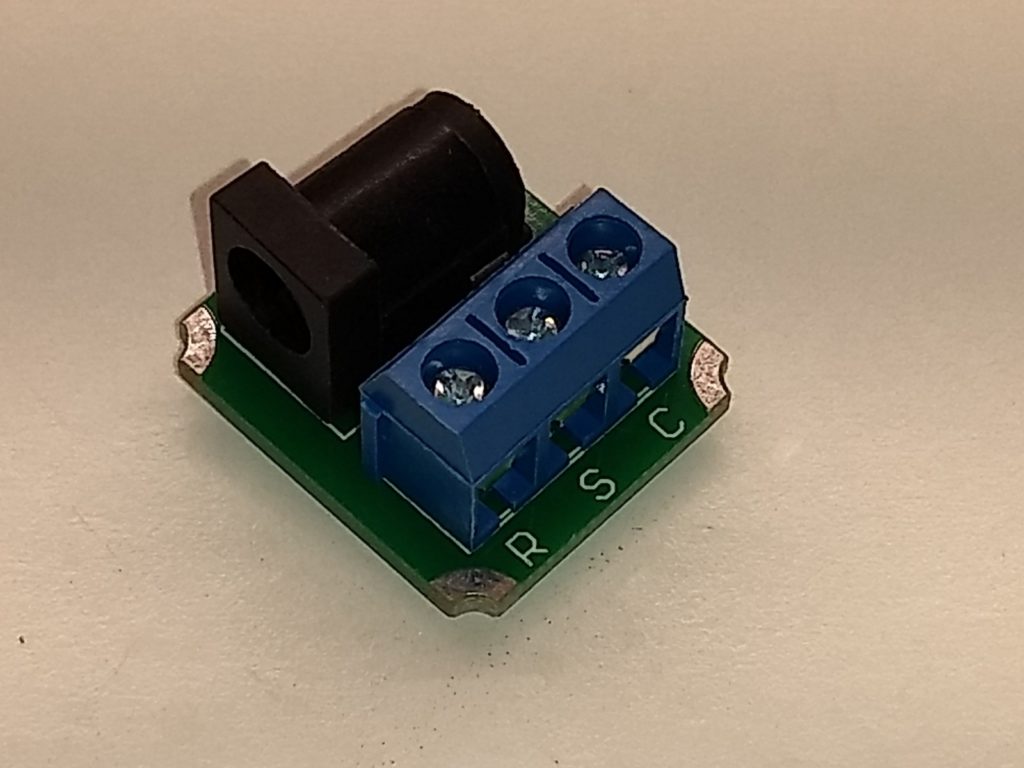
Another “Hobbyist Tools†category product, the Barrel Connector Breakout PCB is small DIY kit that allows electronics hobbyists to use modular barrel connector in their project without having to solder to a female jack/receptacle. The connectors have center, outer and switch connections that are bought out to a 3 pin screw terminal. Mounting holes let you robustly and securely mount the power adapter to your project.
Why do it?
Having a solid, reliable power connection is critical for prototyping electronic projects. Using this adapter makes power connections easy and trouble-free. Have one less thing to worry about in your electronic experiments – keep several of these handy adapters on your bench!
Benefits & Values
Low-cost breakout board provides robust, convenient and reliable power connection for hobby electronics projects.
Who benefits from this kit?
Electronic hobbyists can easily and reliably power their projects. Prototyping engineers can quickly produce proof-of-concept designs. Classrooms can provide project power options that don’t require soldering.
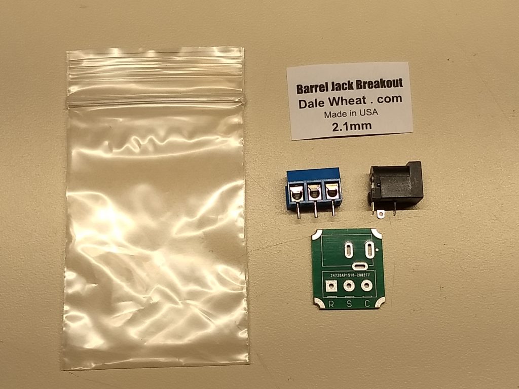
Barrel Jack Breakout board kit (2.1mm variation shown)
What’s included in the kit?
Resealable plastic bag 2″x3″
Printed circuit board
Barrel jack connector (2.1mm or 2.5mm)
3-pin screw terminal block
Kit label
Barrel Jack Breakout Board Kit
The Barrel Jack Breakout kit provides a modular power connection for your project.
2.1mm and 2.5mm versions are available. Assembly is quick and easy. Once assembled, no soldering is required to install or use the Barrel Jack Breakout board with your breadboard project.
In the Before Times, if one of the products in the store was “Out of Stock”, it was not possible to place an order for it. Now some of the lower lead-time products can be backordered from the web store, even if today’s present inventory appears to be depleted.
Other products that have longer lead times, i.e., 30 days or more, are not available to be back ordered.
You Will Know Beforehand
If you place an order for a back ordered product, you will be notified before you place the order. Our intention and goal will be to ship any back ordered product within seven days. You will be notified if it looks like it will take longer than that. You will always have the option of cancelling any part of your order that has been back ordered.
Share Your Thoughts
As always, we really want to know what you think about this new policy change. The hope is that this will make it easier for you to get the products you want, when you want them.
In Part 1 of this series, I introduced you to the RISC-V computer instruction set architecture and described some first steps using an example device. In this article, I continue working with PlatformIO to program the GD32VF103CBT6 chip on the Sipeed Longan Nano development board. Specifically, we’ll use one of the onboard serial ports of the chip for both device programming and communication with the host PC.
Setup for Serial Communication
The GD32V series of chips from GigaDevice offer multiple bootloader options, including:
USB Device Firmware Update (DFU)
Serial bootloader using USART0 or USART1
The USB DFU method was demonstrated in the previous article. A “rolling†button press sequence on the Longan Nano board (“roll UP to UPloadâ€) puts the device in bootloader mode. This time, we’ll use a serial port to both program the device and communicate with the host PC.
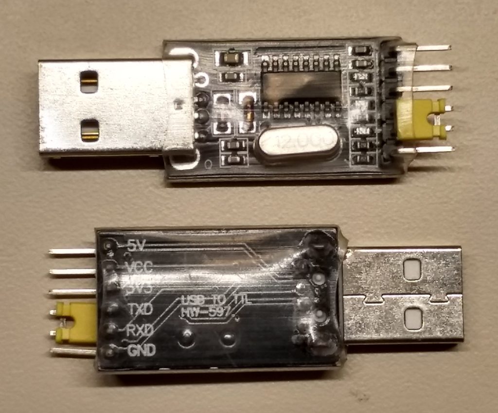
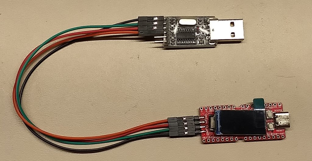
Two changes have to be made to switch over from USB to serial communication. First, we have to connect the serial port (USART0) on the GD32VF103 chip to the host PC via a USB-TTL adapter. You can use any adapter you like, as long as it provides an option to select the output voltage as being 3.3V, to be compatible with the GD32V chip. Here is a photo of the one I used:
USB-TTL adapter
Figure 1. The USB-TTL adapter will connect to the Sipeed Longan Nano. This model uses the CH430G interface chip.
Here are the necessary connections (color selection is entirely up to you):
USB-TTL —- Sipeed Longan Nano
3.3V, 3.3V, orange
GND, GND, black
TXD, R0, red
RXD, T0, green
Coonect the USB-TTL adapter to the Sipeed Longan Nano using four jumpers
Figure 2. Connect USB-TTL adapter to Sipeed Longan Nano. Note that transmit and receive are swapped on both ends.
Next, we change the upload_protocol specified in the project’s platformio.ini file from
upload_protocol = dfu
… to …
upload_protocol = serial
We need not indicate which port to use, baud rate or any other details like that. PlatformIO just figures it all out, which was nice.
I applied these changes first to the existing (and working!) example from the previous article that blinked all three colors of the on-board LED. It’s important to perform the “button roll†first, to prepare the chip for bootloading, before hitting the “Upload†icon. For short demonstration programs such as this, the time to program the device is still quite tolerable, even using the serial port.
A Bad Assumption
Here’s where a Bad Assumption came into play. Since the bootloader had to configure the on-board USART (universal synchronous/asynchronous receiver/transmitter) to communicate to the PC, I assumed that the USART would remain properly initialized, and that we could just start using it.
That turns out not to be the case. Which is OK, really. One shouldn’t depend on someone else’s software to set up one’s environment for one, should one? The bootloader looks to be doing a good job of covering its tracks as it hands off to the application program.
Create a New Project
Let’s create a new project for these further experiments with the Sipeed Longan Nano. In PlatformIO, go to the PlatformIO Home page. This page opens itself by default after you open the application, unless you tell it not to. If the Home page is not already being displayed, click on the PlatformIO icon (alien bug head?) on the left edge of the screen, then select “PIO Home/Open†from the Quick Access menu at the bottom left of the screen. There is also a Home icon on the bottom edge of the screen that looks like a little house. It can take a moment to load this page, because it has to contact the PlatformIO home planet.
On the left edge of the PlatformIO Home tab, you can select the Home icon, then find the “New Project†button in the Quick Access group at the top right. Alternatively, you can select the Projects icon and see a list of your current projects. The “Create New Project†button is at the top right of the screen.
Project Wizard
Either method brings up the Project Wizard dialog. Here you enter a project name and select which board to use. The list of supported boards is large and growing, so just start typing “longan nano†and it will start filtering out the non-matching options. This will pre-populate the “Framework†drop-down with “GigaDevice GD32V SDK†(what we want), as well as allow you to select “Arduinoâ€, which we will explore in a future article. Click the “Finish†button and your new project is set up for you.
Now you have an “empty†project for the GD32V framework, but it’s not really empty. There’s already a folder structure present that is well-organized for PlatformIO’s purposes. You can explore this structure using PlatformIO’s Explorer. Open the Explorer by clicking on the Explorer icon (stacked papers?) at the top left edge of the window.
Create a New Source File
In the Workspace section, expand the folder structure for your newly created project and find the “src†(source code) folder. Right-clicking on the “src†folder brings up a context menu. Select “New File†from this menu. You will see a blank line into which you should type the name of your source code. A good choice here would be “main.câ€, as it will contain our C program’s main() function, but feel free to express yourself. This will open a new editor with a tab at the top of the window.
Enter the following code into the editor
/* main.c
    part of GD32V-USART0 project
    Dale Wheat
    28 Feb 2020
*/

#include "gd32vf103.h"
#include <stdio.h>

int _put_char(int c) {
    usart_data_transmit(USART0, (uint8_t) c);
    while(usart_flag_get(USART0, USART_FLAG_TBE) == RESET);
    return c;
}

void main(void) {

    int i = 0; // iterator

    // initialize USART0

    rcu_periph_clock_enable(RCU_GPIOA);
    rcu_periph_clock_enable(RCU_USART0);
    gpio_init(GPIOA, GPIO_MODE_AF_PP, GPIO_OSPEED_50MHZ, GPIO_PIN_9);
    gpio_init(GPIOA, GPIO_MODE_IN_FLOATING, GPIO_OSPEED_50MHZ, GPIO_PIN_10);

    usart_deinit(USART0);
    usart_baudrate_set(USART0, 9600);
    usart_parity_config(USART0, USART_PM_NONE);
    usart_word_length_set(USART0, USART_WL_8BIT);
    usart_stop_bit_set(USART0, USART_STB_1BIT);
    usart_hardware_flow_rts_config(USART0, USART_RTS_DISABLE);
    usart_hardware_flow_cts_config(USART0, USART_CTS_DISABLE);
    usart_receive_config(USART0, USART_RECEIVE_ENABLE);
    usart_transmit_config(USART0, USART_TRANSMIT_ENABLE);
    usart_enable(USART0);

    while(1) {
        //usart_data_transmit(USART0, '!');
        printf("Hello, GD32V world!  i = %i\n", i);
        i++;
        for(volatile uint32_t n = 0; n < 10000000; n++); // delay
    }
}

// [end-of-file]
Listing 1. Test program for serial port testing
Once you’ve got this code into the editor, be sure to save it using either menu item “File/Save†or Ctrl+S.
Modify Project Configuration File
The Project Wizard created a basic project configuration file for you, named platformio.ini. Select this file using the Explorer and add the following two lines:
build_flags = -ffreestanding
upload_protocol = serial
Listing 2. Add these two lines to your project configuration file.
The first line, build_flags, allows you to send command-line options to the GCC compiler. You may have noticed that the main() function in this example is declared as returning “voidâ€, as is proper and fitting for an embedded application. The C programming language, originally developed for application programs, expects support from an operating system. The default and expected return value type is an “intâ€. To avoid the compiler complaining about this heretical behavior, we pass this option (-ffreestanding) to the compiler and all is well.
The second line, upload_protocol, is more important. Here we assign it a value of “serialâ€. PlatformIO does the rest.
Remember to save your newly-edited configuration file and then we’ll be ready to do a test build and make sure all the pieces are in place.
Time to Build
On the bottom edge of the screen is a toolbar we will find quite handy. To the right of the Home icon is the Build icon (check mark). Click this and PlatformIO will try to build your project. Ideally, you will see the following (or similar) text in the lower part of the window:
CONFIGURATION: https://docs.platformio.org/page/boards/gd32v/sipeed-longan-nano.html
PLATFORM: GigaDevice GD32V 1.1.2 > Sipeed Longan Nano
HARDWARE: GD32VF103CBT6 108MHz, 32KB RAM, 128KB Flash
DEBUG: Current (altera-usb-blaster) External (altera-usb-blaster, gd-link, jlink, rv-link, sipeed-rv-debugger, um232h)
PACKAGES:
 - framework-gd32vf103-sdk 1.0.0
 - toolchain-gd32v 9.2.0
LDF: Library Dependency Finder -> http://bit.ly/configure-pio-ldf
LDF Modes: Finder ~ chain, Compatibility ~ soft
Found 0 compatible libraries
Scanning dependencies...
No dependencies
Building in release mode
`buildhex' is up to date.
Checking size .pio\build\sipeed-longan-nano\firmware.elf
Advanced Memory Usage is available via "PlatformIO Home > Project Inspect"
RAM:   [=         ]   7.0% (used 2310 bytes from 32768 bytes)
Flash: [=         ]   6.5% (used 8456 bytes from 131072 bytes)
========================= [SUCCESS] Took 0.83 seconds ===============================================
Terminal will be reused by tasks, press any key to close it.
Upload the Newly Built Code
If all went well, we are ready to upload this test code to the device. Perform the bootloader “button roll†to prepare the device, then select the Upload icon (left arrow) in the toolbar. You should see this (very long) bunch of stuff appear in the Terminal window at the bottom of the screen:
Configuring upload protocol...
AVAILABLE: altera-usb-blaster, gd-link, jlink, rv-link, serial, sipeed-rv-debugger, um232h
CURRENT: upload_protocol = serial
Looking for upload port...
Auto-detected: COM15
Uploading .pio\build\sipeed-longan-nano\firmware.bin
stm32flash 0.4

http://stm32flash.googlecode.com/
Using Parser : Raw BINARY
Interface serial_w32: 115200 8E1
Version      : 0x30
Option 1     : 0x00
Option 2     : 0x00
Device ID    : 0x0410 (Medium-density)
- RAM        : 20KiB  (512b reserved by bootloader)
- Flash      : 128KiB (sector size: 4x1024)
- Option RAM : 16b
- System RAM : 2KiB
Write to memory
Erasing memory
Wrote address 0x08000100 (3.02%)
Wrote address 0x08000200 (6.05%)
Wrote address 0x08000300 (9.07%)
Wrote address 0x08000400 (12.09%)
Wrote address 0x08000500 (15.12%)
Wrote address 0x08000600 (18.14%)
Wrote address 0x08000700 (21.16%)
Wrote address 0x08000800 (24.19%)
Wrote address 0x08000900 (27.21%)
Wrote address 0x08000a00 (30.23%)
Wrote address 0x08000b00 (33.25%)
Wrote address 0x08000c00 (36.28%)
Wrote address 0x08000d00 (39.30%)
Wrote address 0x08000e00 (42.32%)
Wrote address 0x08000f00 (45.35%)
Wrote address 0x08001000 (48.37%)
Wrote address 0x08001100 (51.39%)
Wrote address 0x08001200 (54.42%)
Wrote address 0x08001300 (57.44%)
Wrote address 0x08001400 (60.46%)
Wrote address 0x08001500 (63.49%)
Wrote address 0x08001600 (66.51%)
Wrote address 0x08001700 (69.53%)
Wrote address 0x08001800 (72.56%)
Wrote address 0x08001900 (75.58%)
Wrote address 0x08001a00 (78.60%)
Wrote address 0x08001b00 (81.62%)
Wrote address 0x08001c00 (84.65%)
Wrote address 0x08001d00 (87.67%)
Wrote address 0x08001e00 (90.69%)
Wrote address 0x08001f00 (93.72%)
Wrote address 0x08002000 (96.74%)
Wrote address 0x08002100 (99.76%)
Wrote address 0x08002114 (100.00%) Done.
GET returns unknown commands (0x 6)
Starting execution at address 0x08000000... done.
================================= [SUCCESS] Took 2.22 seconds ===================================
Terminal will be reused by tasks, press any key to close it.
It’s interesting to me that PlatformIO uses the “stm32flash†program to upload the code. Here we see yet another similarity to the familiar STM32 family of parts from STmicroelectronics that we all know and love (or not). Unfortunately, the link given no longer computes. Also note that the reported RAM (20KiB) is incorrect, (-C8T6 instead of -CBT6?) but does not seem to affect the programming of the flash memory.
Testing the New Code
To see if the code is actually working or not, select the Serial Monitor toolbar icon (electrical plug? South-facing AND gate?). This will launch the serial communications program miniterm within the window at the bottom part of the screen. You should see “Hello, GD32V world!†followed by an ever-incrementing counter, about once a second:
Hello, GD32V world!  i = 300
Hello, GD32V world!  i = 301
Hello, GD32V world!  i = 302
Hello, GD32V world!  i = 303
Hello, GD32V world!  i = 304
Hello, GD32V world!  i = 305
Hello, GD32V world!  i = 306
Hello, GD32V world!  i = 307
Hello, GD32V world!  i = 308
Hello, GD32V world!  i = 309
Hello, GD32V world!  i = 310
Hello, GD32V world!  i = 311
Hello, GD32V world!  i = 312
Hello, GD32V world!  i = 313
Hello, GD32V world!  i = 314
Code Review
Let’s review the code a bit and see what we have.
After a short section of program comments identifying the file, project, author and date, we have a couple of #include statements:
#include "gd32vf103.h"
#include <stdio.h>
The first one defines all the interesting bits of the GD32VF103 chip, as far as pointers to peripherals and other useful information, as well as further linking to other files that bring in all the details about the standard peripheral library, which comes in handy presently.
The second statement gives us access to C’s standard IO (input and output) library, which includes the ever-popular printf() function.
Interfacing with printf()
To actually use the printf() function, we have to define a function called _put_char(). This is because the printf() function itself has no idea of where to send all those formatted characters. In this instance, we want to send them straight out the serial port known as USART0. This is the easiest port to use for this experiment, as these pins are brought out to the header on the edge of the Sipeed Longan Nano board.
The main() Function
From a programmer’s perspective, the fun starts with the main() function. In reality, some system initialization occurs before the main() function starts its work. This includes setting up the stack pointers, initializing the memory areas and cranking up the clock speed.
In our main() function, we declare an integer, i, that will be used as our loop counter later.
Next are the several steps necessary to properly initialize the serial port. This is accomplished using calls to the standard peripheral library, which takes a lot of tedium out of getting things working quickly.
Wake Up, Peripherals!
One thing that might be surprising to embedded programmers coming from, e.g., Arduino or Microchip PIC backgrounds is that almost all of the peripheral devices in the GD32V family, much like the embedded ARM devices, are powered off when the chip begins operation. Each peripheral must be explicitly enabled before use. This saves a lot of power, as unused sections of the chip remain dormant and take little or no power.
Additionally, since most pins of the GD32V device can be either inputs, outputs or serve as connections to the internal peripherals, you have to explicitly define which pins are used for what purposes. Only then do we get to the part where we can set up the individual peripherals to perform as we wish.
USART Configuration
There is a very particular sequence of events that must take place to properly get the USART up and running. All these steps are greatly simplified by using the standard peripheral library calls you see in the example program given. The parameters (9600 baud, 8 data bits, no parity, plus others) match the default communication settings of the miniterm program invoked by PlatformIO in its Serial Monitor function.
The Endless Loop
Most embedded applications follow a very simple pattern: perform some initialization, then go into a perpetual loop. This has been immortalized in Arduino’s setup() and loop() functions. We have our own infinite loop in our example, consisting of a while(1) control block. Since the constant “1†always evaluates to “true†by the C compiler, this loop will continue until something drastic happens. This could be an external reset, interrupt or ultimately power loss.
Within the loop, look for a statement that has been commented out, namely:
//usart_data_transmit(USART0, '!');
This was a call to the standard peripheral library that sent a single character to the USART for transmission. I used this for the first test of the program, before adding the printf() support. Upon opening the Serial Monitor, I was rewarded with a trail of exclamation points marching across the screen. Success!
Then Things Got Weird
Like Edison, I couldn’t be happy with my first glowing light bulb: I had to mess with it until it broke. Not surprisingly, this didn’t take long.
The first thing I tried was to increase the delay time between exclamation points. Simply adding a zero to the constant comparison value in the for() loop had no obvious effect on the pace of the points. Another zero also had no effect. More annoyed than puzzled, I proceeded with setting up support for formatted output using the printf() function from C’s standard input and output library.
Really Weird
Adding the printf() function support was simply a matter of adding the _put_char() function into the program. Nice! I was happy for many milliseconds as I watched my formatted “Hello, world!†statements scroll down the page. Oddly, however, the “i = 0†counter stayed at, oddly, zero. Did I forget to increment the variable? I’ve done that before. But no, that was not the case.
Some amount of time and head-scratching elapsed. This did not make sense. Surely I hadn’t run into some subtle compiler bug already. Then it hit me.
When Does i = 0?
The only time that the variable i should equal zero is right after the program starts… which happens to be right after the power comes on (or the reset button is pushed, which wasn’t happening). Glancing at the power LED on the Sipeed Longan Nano bard, I saw that it was flickering. Not good. And yet, it was good, as this would explain both the non-incrementing counter as well as the lack of timing changes induced by orders of magnitude different parameters previously seen.
Ultimately, the issue was that I had plugged the USB-TTL adapter into a USB hub, and not directly into my PC. It seems that the voltage drop through the hub, then through the voltage regulator on the USB-TTL adapter and then through the jumper wires to the development board resulted in a low-voltage condition for the system. Plugging the USB-TTL adapter directly into my PC solved the problem.
Conclusion
We now have two proven and (relatively) convenient methods to program the device: USB DFU and serial. Additionally, we have a bi-directional communication channel to the host PC that we can use for whatever we want, including simple debugging.
Another important advantage, which we had in the previous article but didn’t really explore, was access to the complete standard peripheral library for this device. This will obviate many hours of tedious research into datasheets, which will please some and annoy others.
Next Time
Continuing in this series of articles, I hope to explore a more in-depth method of debugging these chips. Stay tuned!
Things I Learned
PlatformIO is a rich environment that can be overwhelming at times, especially for new users. Additionally, there are almost always more than one way to accomplish any specific tasks, which is both useful and confusing.
Google Docs has a short but non-trivial learning curve for me. There are very few options when it comes to text styles. One of the default paragraph styles (“Normal textâ€) needed some extra space after each paragraph. This was easy to set using menu item “Format/Line spacing/Add space after paragraphâ€. Then selecting menu item “Format/Paragraph styles/Options/Save as my default styles†should make this change persistent.
My laptop battery seemed to fail after about 30 minutes, with what I thought was a full charge. These things happen, as batteries are very much a consumable thing. Another full charge back at the lab and the behavior occurred again. Yet another charge later and it was back to what appeared to be its nominal runtime, which was traditionally 3-4 hours. How was I to measure the specific behavior of the battery without sitting in front of it for hours and watching it? A simple solution was to write a small program that updated a file every minute and then look at that file after the battery discharged enough to shut down the laptop. This was my first attempt to characterise this phenomenon based on observable data.
How Did I Get To This Point?
Time out of the office was once time unproductive for me. If I wasn’t sitting in front of my desktop computer, how was I supposed to get any work done? Then it occurred to me that, since I actually own a “portable computerâ€, i.e., a laptop, I really didn’t have an excuse. So as an experiment, I took my trusty laptop with me on a tedious errand and proposed to write a couple of short articles.
As described above, I enjoyed about half an hour of reasonable performance with my laptop, without the benefit of being plugged into the wall. I should mention that this is an older model, an ASUS R500V with an Intel Core i7 processor and a solid state drive. The “MFD†(manufactured?) date on a sticker on the bottom (after some Chinese characters which I still can’t read) said “2012-11â€, so I would assume that meant November of 2012, which seems about right. As of this writing, my laptop would be just over 7 years old.
Blame the Battery
Nothing lasts forever, especially consumables like rechargeable batteries. The prudent thing to do would be to order a replacement and thus solve the problem, which I did. In a few days, I expect delivery of a replacement battery, and that should be that.
Another reason to take this blunt and direct approach to problem-solving (lacking style or subtlety) is that laptop batteries are now cheap. They used to hover around the US$100 level and can now be had for under $20, which often includes shipping. Problem solved, move along, nothing to see here.
Questioning My Motives
Yet I wondered. I made this decision based on irritation and the fear of losing faith in (and possibly use of) my essential tools. How could I make a more informed decision in the absence of cold, hard facts? Having some solid run-time data would be a good start.
What I didn’t want to do was have this turn into “a whole thingâ€, as I often say. I had already performed a handful of charge-discharge cycles on the laptop-charger-battery system, but was not meticulously noting any actual times. How could I do this without becoming a virtual slave to my ageing tools?
One More Datapoint Wouldn’t Hurt
I have my best technological ideas when I am furthest from the lab where I could take action on them. Weird it is, but here we are. One experiment would be to run the laptop to exhaustion, and note the elapsed time. This is problematic, as the laptop doesn’t do any useful work after the power fails.
A more indirect approach was needed. Very quickly, a plan erupted into my mind. I could write a program that updated a status file with the current time and date. The file would need to be opened, written and closed as quickly as possible. Doing so will minimize the risk of the eventual and inevitable power failure would occur during the update itself, possibly corrupting the file or, worse, the file system itself.
Empowering Technologies
“If all you have is a hammer, everything begins to look like a nailâ€.
This truism has another face: The more art and skill you possess, the more options you have. One “empowering technology†that I have is the ability to code in BASIC. Luckily for me, I had early opportunities in life to learn about programming, long before “home computers†became available.
As a teeneager, I worked over the summer at a minicomputer (yes, that was a thing) manufacturer in Richardson, Texas called Computer Automation. A bonus of this low-paying job was that I could borrow an Alpha 16 computer, complete with teletype machine, for the duration of the summer. It boasted a very complete version of the BASIC programming language. I would noodle on this contraption until the wee hours of the morning. Surely this had to be distracting for the rest of my family, as a Teletype makes quite the clatter.
To this day, BASIC has its fans and detractors. Moving from whatever version of BASIC the Alpha 16 was running, to the Atari BASIC cartridge (floating point! graphics!), to IBM’s BASICA, GW-BASIC, QBASIC, then QuickBASIC (compiled!), I always had a quick and (sometimes) dirty method to whip up some code to accomplish small tasks. Very empowering, indeed!
But This is 2020 Frowny Face Question Face
While I have also learned to program in C and a little bit in Python, sometimes you only want to perform a simple function. Setting up those environments and keeping up with their ever-changing capabilities can be exhausting, especially to old folk like me.
Enter QB64
QB64 calls itself “QB64 is a modern extended BASIC programming language that retains QBasic/QuickBASIC 4.5 compatibility and compiles native binaries for Windows, Linux, and macOSâ€. You can find out more about it on their web site QB64.org. QB64 is distributed under the MIT license, though it took an email to the support team to clarify this.
Figure 1. The QB64 home screen. Look familiar?
For those of you that remember QBASIC and similar programming environments from the long, long ago, the QB64 home screen should look rather familiar. Just like most integrated development environments (IDEs) of today all start to look alike (I’m looking at you, Eclipse), there’s only so many ways to make a text-based application work that supports both a menu system and a multi-document interface (MDI).
QB64 version 1.4, the current stable version of the program as of this writing, is what I will be using for this project.
Program Outline
A simple program should be defined (or more precisely, be able to be defined) with a short outline. Here’s what I want this program to do, in a nutshell:
Document program function, author, date, license and possibly revision history
Open a unique filename in a known location
Write a short statement (plain text) as a heading describing the function of the file.
Close the file
Write a status message once a minute:
Open the file
Write the update record at the end of the file
Close the file
Repeat from Step 5, ad infinitum (because I don’t know the fancy Latin phrase for “until exhaustionâ€).
Bonus Points: Display status messages on the console so we can “see†what’s going on with the program, as well as a command-line option to disable said notices.
Program Documentation
“Self-documenting code†is an oxymoron. If it’s code, it’s not readable; that’s what the word code means. If it’s readable, it’s not code. If it isn’t readable, it isn’t self-documenting. Just sayin’.
However, let’s leave a few breadcrumbs for later generations in the form a few program comments. As learned in your very first computer programming class (assuming that happened), the first few lines of your source code (i.e., the original, human-readable document that will subsequently be ground up into ones and zeros later) should contain the file name, the program or project to which it belongs, the purpose of the file (if not obvious) and the author’s name and perhaps contact information. Bonus points will be awarded for identifying the licensing terms under which the work is to be published and keeping some sort of version-tracking information in the source code as well.
Here’s what I thought would be a good start to the program:
Figure 2. The program header (using comments). File name, project name, author, contact information, no license or revision history.
Omitting the licensing terms for this soon-to-be-published code is my sneaky way of getting people to contact me if they are curious about using the code for their own purposes. I wasn’t going to hear from those nogoodniks that were going to outright steal it, in any case.
Don’t fret, Dear Reader, that you are not able to scrape the code itself from these (graphic) screen shots. I will post the complete code as in a block near the end of the article as well as offer a direct download link to the most recent version.
Satisfying outline item number one (so-called self-documentation), to a certain extent, we move on to number two, creating a unique file name for this experimental run.
Asking For Help
If your memory, like mine, does not retain the seemingly infinite number of BASIC keywords and their usage, fear not. You can access detailed help in two ways.
The QB64 web site contains a wiki that describes the available functions by keyword or usage:
The same information is contained within the application itself. Select menu item “Help/Keywords by usage†and see the following screen.
Figure 3. Built-in help from within the QB64 application.
You can then mouse around, clicking on the links, and explore the available help topics. This is a very handy feature of the original QuickBASIC as well as QB64.
The Program Begins
At the beginning of program execution, we should emit a line or two on the console describing the program’s name and intended function. This gives the user immediate feedback that the program is running correctly.
For our purposes, a simple statement should suffice:
“Battery Test vX.X starting…â€
If we are to use program version numbers, we should define them near the top of the primary source file as CONST data types, so that they cannot be subsequently modified as the program executes.
Using this technique, you can change the program version number once at the top of the code and it will automatically be updated throughout, without having to hunt for every occurrence.
If you run the application now, you will be greeted with a simple console screen with the words “Battery Test v0.0†at the top and “Press any key to continue†and the bottom.
Unique File Names
Once upon a time, I used to write programs for the IBM PC that called native functions of the operating system. One of the interesting functions provided by MS-DOS 3.0 and later, for example, was the “Create Unique Temporary File†command, or “INT 21h function 5Ah†to those in the know. You would give this function a specific sub-directory and it would return a filename that was not currently being used within that folder. This was useful to avoid over-writing any other file. The resulting filename was usually gibberish, but since they were supposedly temporary in nature, it didn’t really matter much.
Today QB64 does not support this function, so we have to try a different approach. What we can do today is create a filename that ought to be as-yet-unused, then check to see if it truly is not yet used, then use that. If it is already in use, for whatever reason, we try again with a slightly different file name.
Making Up a Fake As-Yet-Unused Name
Unlike the Bad Old Days, we can use long file names with our programs. Now by “longâ€, I mean more than the “8.3†format of our ancestors. Ask an Old Person; they will tell you all about it.
Ideally, each run of this program will create its own status file. We can, of course, delete all these files once the novelty wears off, but only after carefully examining the data and drawing what conclusions we may.
To lessen the chances of stepping on anyone else’s files, we’ll prefix our file name with the name of our little test program, i.e., “Battery Testâ€. We then append the current time and date, which ought to make it unique. However, let’s not assume.
“Let’s Not Guess; Let’s Measure!â€
These steps are all straight-forward when using QB64. First, we prepare a candidate status file name using our predetermined suffix (i.e., program name) and the current date and time, with the file extension “.TXT†to let future visitors know it’s a “text†file.
Unfortunately, our naive conglomeration will not work as a filename, because the BASIC function TIME$ returns a STRING variable that contains a human-readable value, e.g., “01:02:03â€. While colons help the human eye to separate the constituent values, they do not play nice with legacy file systems such as MS-DOS, upon which Windows 10 depends.
We can change the offending colons to (almost) anything else, so let’s change them to dashes:
Now we have a file name that Windows 10 will tolerate.
But Is It Unique?
While QB64 won’t generate a unique file name out of thin air for us, it will tell us if a given file name already exists or not, using the _FILEEXISTS(filename$) function. This function returns a “0†value (for false) if the file does not exist in the current folder, or a “-1†(for true) if it does.
We test this assumption of uniqueness with a simple IF statement. Note that here we are only interested in the case where the file name is not unique. If it is already unique, we should continue with the rest of the program.
Supposing that, for some reason, the file name is not unique, a DO … LOOP UNTIL control structure increments a variable, n, appending it (within parentheses) to the candidate file name, until uniqueness occurs.
IF _FILEEXISTS(filename$) = -1 THEN
    n = 0
    DO
        n = n + 1
        filename$ = PROGRAM_NAME + " - " + DATE$ + " - " + alt_time$ + " (" + STR$(n) + ").TXT"
    LOOP WHILE _FILEEXISTS(filename$)
END IF
Now It Is Unique
Either the file name was originally unique, or a unique combination of the candidate file name with appended iterator n eventually was. In either case, we announce the name of the file on the console.
PRINT "Using status file " + filename$
Emit Column Headings
A good way to analyze the resulting data file would be to import it into a spreadsheet program and generate some pretty graphs. To make this process easier for the spreadsheet, we’ll name the forthcoming data columns in the first line.
Now we can output the file headers, being sure to close the file afterwards. Remember, the battery is going to fail at any time now! Let’s leave things tidy, shall we?
' Open file for output; write caption; close file

file_handle = FREEFILE
OPEN filename$ FOR OUTPUT AS file_handle
PRINT #file_handle, PROGRAM_NAME + " Date, Time"
CLOSE file_handle
The Main Loop
Here is where the program should spend the majority of its time. Once a minute (or until we decide on a more reasonable time period), the status file will be opened and a new line appended to the end, containing the date and time.
One way to achieve this timing between updates would be to wait for the minute number on the system-reported time to change. The reason this would be a Bad Thing is that it would run continuously, eating up all available processor cycles while doing so. Another, better, option would be to use the _DELAY function, which takes a parameter that can be expressed in fractional seconds. It also yields any remaining CPU cycles back to the operating system so other tasks can execute. We want just shy of one minute, or sixty seconds, so we pass an argument of 59.99 seconds to the function. This will eventually result in either a roll-over or roll-under event to occur in the log, specifically in the seconds column. For our purposes, this is acceptable.
' The main loop

DO
    file_handle = FREEFILE
    OPEN filename$ FOR APPEND AS file_handle
    PRINT DATE$ + ", " + TIME$ ' to console
    PRINT #file_handle, DATE$ + ", " + TIME$ ' to file
    CLOSE file_handle

    _DELAY 59.99 ' 59.99 seconds is most of a minute
LOOP
Program Testing
Now that we have a potentially working program, let’s set it to work and see what it does. With the battery reporting to be about 75% charged, I unplugged it from the charger and started the logging program. Then I just walked away.
Later, I found the laptop powered down, as expected. Looking at the status log, I saw that the first entry was made at “02-24-2020, 14:59:59â€, and the last one was recorded at “02-24-2020, 16:51:59â€. So right away I decided that the program should be calculating the elapsed time and recording it for me. Do I have time to do clock math? No, I do not.
Well, for right now, I guess I can do some clock math. First, the starting and ending dates are the same, so that makes it a bit easier. 16:51:59 minus 14:59:59 is 1:52:00, so there we have a nearly two hour run time with what was reported to be a 75% charge. All I have to do now is wait the estimated (so it tells me) 1:32:00 for the battery to fully charge and then I can repeat the experiment with a 100% charge. In the meantime, I can update the program to calculate the elapsed time for me.
A Few Final Tweaks to the Program
I added a minute counter to the main loop, so we don’t have to tax our big brains with clock math. The resulting number is added to the status report each minute. I spent some time trying to get the number of minutes to print out using “H:MM†format, but got frustrated and gave up. This would be trivial using C’s printf() function, but that’s not what I’m using here. The number of minutes is close enough. Fractional hours would have worked, as well.
After several runs, I discovered that the laptop was set to automatically power down after two hours when running on the battery. I created a new battery profile for testing to exhaustion and ran some more charge+discharge cycles.
I really wanted to add the system’s estimated battery power remaining percentage and run time, but this is where I decided to stop. Sadly, importing these status files into a spreadsheet program and creating a graph only produces a straight, diagonal line, indicating the steady march of time during each test. Having some fun statistics like estimated run time would make the graphs more entertaining, at least.
Program Listing
As promised, here’s the program listing for this little test application.
IF _FILEEXISTS(filename$) = -1 THEN n = 0 DO n = n + 1 filename$ = PROGRAM_NAME + " - " + DATE$ + " - " + alt_time$ + " (" + STR$(n) + ").TXT" LOOP WHILE _FILEEXISTS(filename$) END IF
PRINT "Using status file " + filename$
' Open file for output; write caption; close file
file_handle = FREEFILE OPEN filename$ FOR OUTPUT AS file_handle PRINT #file_handle, PROGRAM_NAME + " Date, Time, Elapsed (minutes)" CLOSE file_handle
' The main loop
minutes = 0 ' reset count of elapsed minutes
DO
file_handle = FREEFILE OPEN filename$ FOR APPEND AS file_handle PRINT #file_handle, DATE$ + ", " + TIME$ + ", " + STR$(minutes) ' to file CLOSE file_handle
QB64 offers some more versatile timing options, such as the TIMER and ON TIMER functions. These would make the periodic update event asynchronous to the setup code, and would more than likely eliminate the roll-over or roll-under anomalies of the current method.
Battery Runtime Guessing
When running Windows on a laptop, the user can hover the mouse over the battery icon in the notification tray to see the estimated run time remaining on the current charge.
Figure [4] Windows 10 estimates remaining battery capacity
By accessing a Windows DLL via QB64, we could add this information to the status file that is created. Other operating systems should offer similar guesses.
Command Line Parameters
To tailor each run of this little program, we could allow the use of “command line parametersâ€. Doing so would allow us to modify the program’s behavior without having to alter the original source code each time.
Some options that come to mind:
-v for Verbosity
-p for Path of status file
-n for alternate name for status file
-m for maximum run time limit
-t for time period between status updates
Surely you’ve already thought of some useful additions, yourself. These options would need to be handled at the beginning of the program.
Other Solutions
Some of you might, by this point, be thinking, “But you could have much easierly (now a word) done it using [x], where x is some other technology instead of BASIC, or a different flavor of BASIC. A DOS batch file, some Windows application for the very purpose… the list goes on. You are entirely correct to say so. But this was the story of how I did it this way.
Things I Learned While Telling You This Story
If you installed QB64 in a folder that requires “administrative privilegesâ€, your resultant executables might not execute normally. Installing in a folder where you already have complete freedom (i.e., write privilege) is advised.
Using Google Docs for quick articles such as this one has a small but measurable learning curve. For example, keeping up with word count is important to a professional writer. While you can check your word count with a menu item (Tools/Word Count, or Ctrl+Shift+C), you can also check the box on the resulting dialog box marked “Display word count while typingâ€. This wedges a word count box in the lower left corner of the screen. Bonus: It’s actually a drop-down selection box. Clicking on it gives you the totals for pages, words and characters (with and without counting spaces, if that matters to you). Unfortunately, this setting is not persistent. Also, once you get past a certain length, the post-it widget no longer works.
Using keyboard shortcuts in Google Docs (or any application) is always good from someone who is communicating mostly via the keyboard. Accepting spell-check and grammar-check suggestions is trivial using a mouse (just hover, then click) but the keyboard-only version is a bit cumbersome: Cursor-key over to the offending word or phrase, Ctrl+Shift+\, then down arrow, then [Enter]. Yikes! But it keeps my hands on the keyboard, where I want them. One day muscle memory will do this for me.
I’m glad I took this little diversion. I’ve got a better understanding of how well (or not) my laptop battery performs. I also enjoyed working with QB64. Not all of the tools from my past can still hold water these days. For example, once upon a time I could (correctly) adjust the alignment magnets on the back of a cathode ray tube. Ah, good times.
QB64 has proven to be a useful tool for me for writing simple programs that perform simple functions. This leverages my misspent youth as a BASIC programmer. Having browsed through QB64’s list of other functions, I think it would be fun to write more ambitious applications.
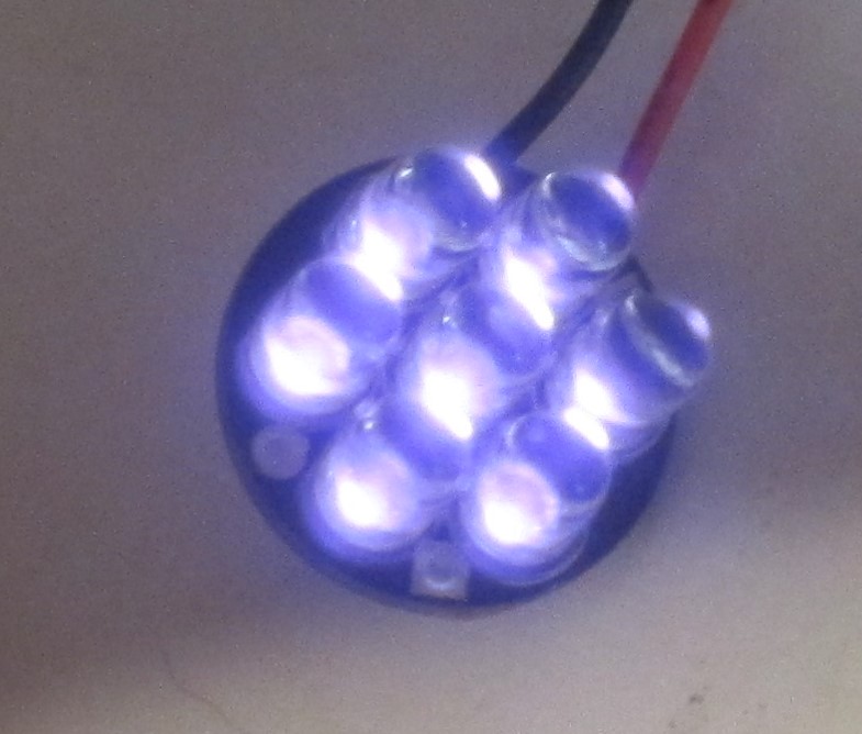
Yes, Astute Reader, you have caught me in, shall we say, an “inconsistencyâ€. This product is not “new”, but it is “new to the store”. I have been designing and selling infrared (IR) spotlight kits for decades now. In the past, I was mostly producing these for wholesale customers like BG Micro. Since I have several different models in stock now, I thought I would start making them available in the web store here:
The Mini7Plus IR Spotlight is a compact, low-power infrared (IR) LED array that runs on 12VDC. The round printed circuit board (PCB) is a tiny 0.75 inches (19.05 mm) in diameter; it’s the same size as a US penny. The Mini7Plus kit contains a quality PCB, seven (7) high-power infrared LEDs, a current limiting resistor and two leads for power.
Product Variations
We offer this product with three (3) different wavelengths and two (2) different beam angles. Wavelength, usually expressed in nanometers or nm, determines the “color†of the infrared light. You need to know which wavelength your camera can detect. The beam angle refers to the spread of light as you get farther away from the LEDs. A 20° beam angle is a fairly tight “spotlight†effect, whereas a 50º angle is more of a “floodlightâ€.
Why do it?
Do you need a compact and reliable source of infrared illumination that runs on 12V? Use it for covert and semi-covert surveillance of small spaces, such as inside your car or under your house. The Mini7Plus IR Spotlight is a reliable and robust source of infrared light for your project.
Value & benefits:
Low-cost kit is easy to assemble and provides thousands of hours of continuous operation. Illuminate small spaces discreetly, such as small animal habitat without generating distracting visible light or excessive heat.
Who benefits?
Photographers and videographers can use the Mini7Plus IR Spotlight to illuminate otherwise invisible worlds. Property owners can use certain surveillance cameras that can pick up the light that is mostly invisible to the human eye. Scientists can use infrared light in experiments to observe nocturnal behaviors.
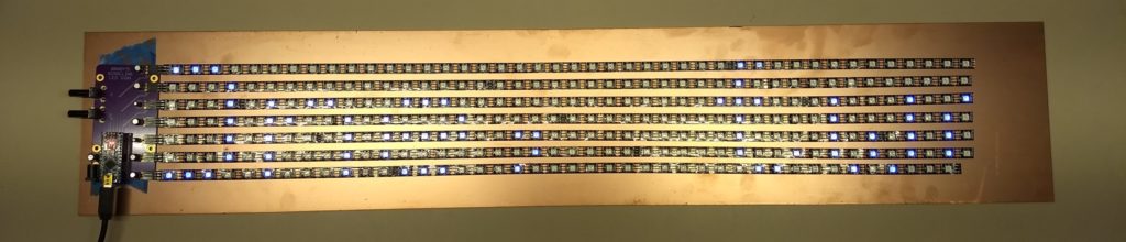
The Scrolling LED Sign kit is an Arduino-powered scrolling LED sign using NeoPixel LED strips. Big, bright messages can be extended long as you want it. This kit lets you connect your Arduino Nano to the popular NeoPixel/WS2812B LED strips. You will also need an external, regulated +5VDC power supply if you use more than around 300 LEDs in your sign.
Why Do It?
Animated GIF of glowy LED strip
You know you want a bunch of bright, colorful LEDs shouting out your message for all kind, sensitive and literate beings to see. This is a fun and very eye-catching project. Grab all the attention with this gorgeous, colorful sign.
Benefit/Value
Store-bought LED signs are expensive and hard to program. You can make this sign a big or as small as you like. Go wild with colors and get your message seen by lots of folks, assuming they can 1) see and 2) read.
Dale’s Scrolling LED Sign, shown with additional components not included with the kit
Who Benefits?
Electronic hobbyists love to build attention-getting projects. Venue operators like to be able to disseminate information in an attractive and mesmerising way. Clubs and groups will stand out with their super-bright, super-colorful signs.
Specifications:
The Scrolling LED Sign kit requires the following additional components, not included with the kit:
Arduino Nano
NeoPixel/WS2812B LED strips with attached header pins
USB cable to power and program the Arduino Nano
External regulated +5VDC power supply (if you use more than 300 or so LEDs)
Something wide and flat to mount the LED strips and driver board
More Details About the Project/Product Transisiton
I’ve written a detailed blog post about how this product came to be. It started out as a project for my friend and inspiration Brady Pamplin, which is why you sometimes see it referred to as “Brady’s Scrolling LED Sign”.